We have an excellent technical team, our products in quality and quantity will make you satisfied, welcome to buy
Views: 6 Author: Site Editor Publish Time: 2008-04-02 Origin: Site
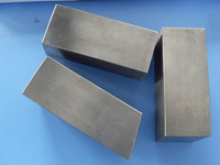
The variety of milling cutters available helps make milling a versatile machining process. Cutters are made in a large range of sizes. Milling cutters are made from High Speed Steel (HSS), others are carbide tipped and many are replaceable or indexable inserts.
Periphery milling cutters — Periphery milling cutters are usually arbor-mounted to perform various operations. Common high-speed steel milling cutters include the staggered tooth cutter, side-milling cutter, plain-milling cutter, single-angle milling cutter, double-angle milling cutter, convex milling cutter, concave milling cutter, and corner-rounded milling cutter.
Light-duty plain mill — A general-purpose cutter for peripheral milling operations. Narrow cutters have straight teeth, while wide ones have helical teeth.
Heavy-duty plain mill — Similar to the light duty mill except that it is used for higher rates of metal removal. To aid it in this function, the teeth are more widely spaced and the helix angle is increased to about 45 degrees.
Side milling cutter — Has a cutting edge on the sides as well as on the periphery. This allows the cutter to mill slots.
Half-side milling cutter — Same as the one previously described except that cutting edges are provided on a single side. It is used for milling shoulders. Two cutters of this type are often mounted on a single arbor for straddle milling.
Stagger-tooth side mill — Same as the side-milling cutter except that the teeth are staggered so that every other tooth cuts on a given side of the slot. This allows deep, heavy-duty cuts to be taken.
Angle cutters — The peripheral cutting edges lie on a cone rather than on a cylinder. A single or double angle may be provided.
Shell endmill — Has peripheral cutting edges plus face cutting edges on one end. It has a hole through it for a bolt to secure it to the spindle.
Form mill — A peripheral cutter whose edge is shaped to produce a special configuration on the surface. One example is the gear tooth cutter. The exact contour of the cutting edge of a form mill is reproduced on the surface of the workpiece.
End-milling cutters — End mills can be used on vertical and horizontal milling machines for a variety of facing, slotting and profiling operations. Solid end mills are made from high-speed steel or sintered carbide. Other types, such as shell end mills and fly cutters, consist of cutting tools that are bolted or otherwise fastened to adapters.
Solid end mills — Solid end mills have two, three, four, or more flutes and cutting edges on the end and the periphery. Two flute end mills can be fed directly along their longitudinal axis into solid material because the cutting faces on the end meet. Three and four fluted cutters with one end cutting edge that extends past the center of the cutter can also be fed directly into solid material.
Solid end mills are double or single ended, with straight or tapered shanks. The end mill can be of the stub type, with short cutting flutes, or of the extra long type for reaching into deep cavities. On end mills designed for effective cutting of aluminum, the helix angle is increased for improved shearing action and chip removal, and the flutes may be polished.
Special end mills — Ball end mills are available in diameters ranging from 1/32 to 2-1/2 in., in single and double-ended types. Single purpose end mills such as Woodruff key-seat cutters, corner rounding cutters, and dovetail cutters are used on both vertical and horizontal milling machines. They are usually made of high-speed steel and may have straight or tapered shanks.
Milling cutter nomenclature — As far as metal cutting action is concerned, the pertinent angles on the tooth are those that define the configuration of the cutting edge, the orientation of the tooth face, and the relief to prevent rubbing on the land.
Outside diameter — The diameter of a circle passing through the peripheral cutting edges. It is the dimension used in conjunction with the spindle speed to find the cutting speed (SFPM).
Root diameter — This diameter is measured on a circle passing through the bottom of the fillets of the teeth.
Tooth — The tooth is the part of the cutter starting at the body and ending with the peripheral cutting edge. Replaceable teeth are called inserts.
Tooth face — The tooth face is the surface between the fillet and the cutting edge, where the chip slides during its formation.
Land — The area behind the cutting edge on the tooth that is relieved to avoid interference is called the land.
Flute — The flute is the space provided for chip flow between the teeth.
Gash angle — The gash angle is measured between the tooth face and the back of the tooth immediately ahead.
Fillet — The fillet is the radius at the bottom of the flute, provided to allow chip flow and chip curling.
The terms defined above apply primarily to milling cutters, particularly to plain milling cutters. In defining the configuration of the teeth on the cutter, the following terms are important.
Peripheral cutting edge — The cutting edge aligned principally in the direction of the cutter axis is called the peripheral cutting edge. In peripheral milling, it is this edge that removes the metal.
Face cutting edge — The face cutting edge is the metal removing edge aligned primarily in a radial direction. In side milling and face milling, this edge actually forms the new surface, although the peripheral cutting edge may still be removing most of the metal. It corresponds to the end cutting edge on single point tools.
Relief angle — This angle is measured between the land and a tangent to the cutting edge at the periphery.
Clearance angle — Is provided to make room for chips, thus forming the flute.
Radial rake angle — The angle between the tooth face and a cutter radius, measured in a plane normal to the cutter axis.
Axial rake angle — Measured between the peripheral cutting edge and the axis of the cutter, when looking radially at the point of intersection.
Blade setting angle — When a slot is provided in the cutter body for a blade, the angle between the base of the slot and the cutter axis is called the blade setting angle.
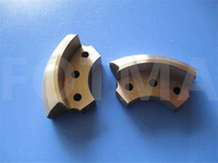
Indexable milling cutters
There are a variety of clamping systems for indexable inserts in milling cutter bodies.
Wedge clamping— Milling inserts have been clamped using wedges for many years in the cutting tool industry. This principle is generally applied in one of the following ways: either the wedge is designed and oriented to support the insert as it is clamped, or the wedge clamps on the cutting face of the insert, forcing the insert against the milling body. When the wedge is used to support the insert, the wedge must absorb all of the force generated during the cut. This is why wedge clamping on the cutting face of the insert is preferred, since this method transfers the loads generated by the cut through the insert and into the cutter body.
The wedge clamp system however, has two distinct disadvantages. First, the wedge covers almost half of the insert cutting face, thus obstructing normal chip flow while producing premature cutter body wear, and secondly, high clamping forces causing clamping element and cutter body deformation can and often will result. The excessive clamping forces can cause enough cutter body distortion that in some cases when loading inserts into a milling body, the last insert slot will have narrowed to a point where the last insert will not fit into the body. When this occurs, several of the inserts already loaded are removed and reset. Wedge clamping can be used to clamp individual inserts or indexable and replaceable milling cutter cartridges.
Screw clamping— This method of clamping is used in conjunction with an insert that has a pressed countersink or counterbore. A torque screw is often used to eccentrically mount and force the insert against the insert pocket walls.
Screw clamping is excellent for small diameter end mills where space is at a premium. It also provides an open unhampered path for chips to flow free of wedges or any other obstructive hardware. Screw clamping produces lower clamping forces than those attained with the wedge clamping system. However, when the cutting edge temperature rises significantly, the insert frequently expands and causes an undesirable retightening effect, increasing the torque required to unlock the insert screw. The screw clamping method can be used on indexable ball milling cutters or on indexable insert slotting and face milling cutters.
content is empty!